Ray marching in LOVR
Martino Trapanotto / August 2024 (2857 Words, 16 Minutes)
Some context
Rendering a 3D scene is not an easy task. 3D geometry elements, light sources, surfaces, textures, reflections, indirect lighting, occlusion and more must be made to interact until a sensible 2D image is produced. And this must be done fast, possibly real time if we want to make something interactive. So, a wide range of techniques got developed in history, trying to achieve this as fast and as accurately as possible.
The most common and widely known solutions for real time rendering is Rasterization, a technique that focuses first on speed and accurate geometry. Here, 3D models, usually represented by sets of triangles called meshes, are projected onto the 2D view. This gives us a clear mapping between 3D geometry and 2D pixels, but lacks anything more, like color or lights. These are calculated per-pixel by a Pixel Shader, or Fragment Shader, utilizing information about the visible 3D element such as texture, UV coordinates, normal vectors, shadow maps and more.

The technique is fast, and has been the cornerstone of real time graphics for decades. But recreating realistic lighting effects is computationally expensive and very difficult, especially complex lighting effects or good global illumination.
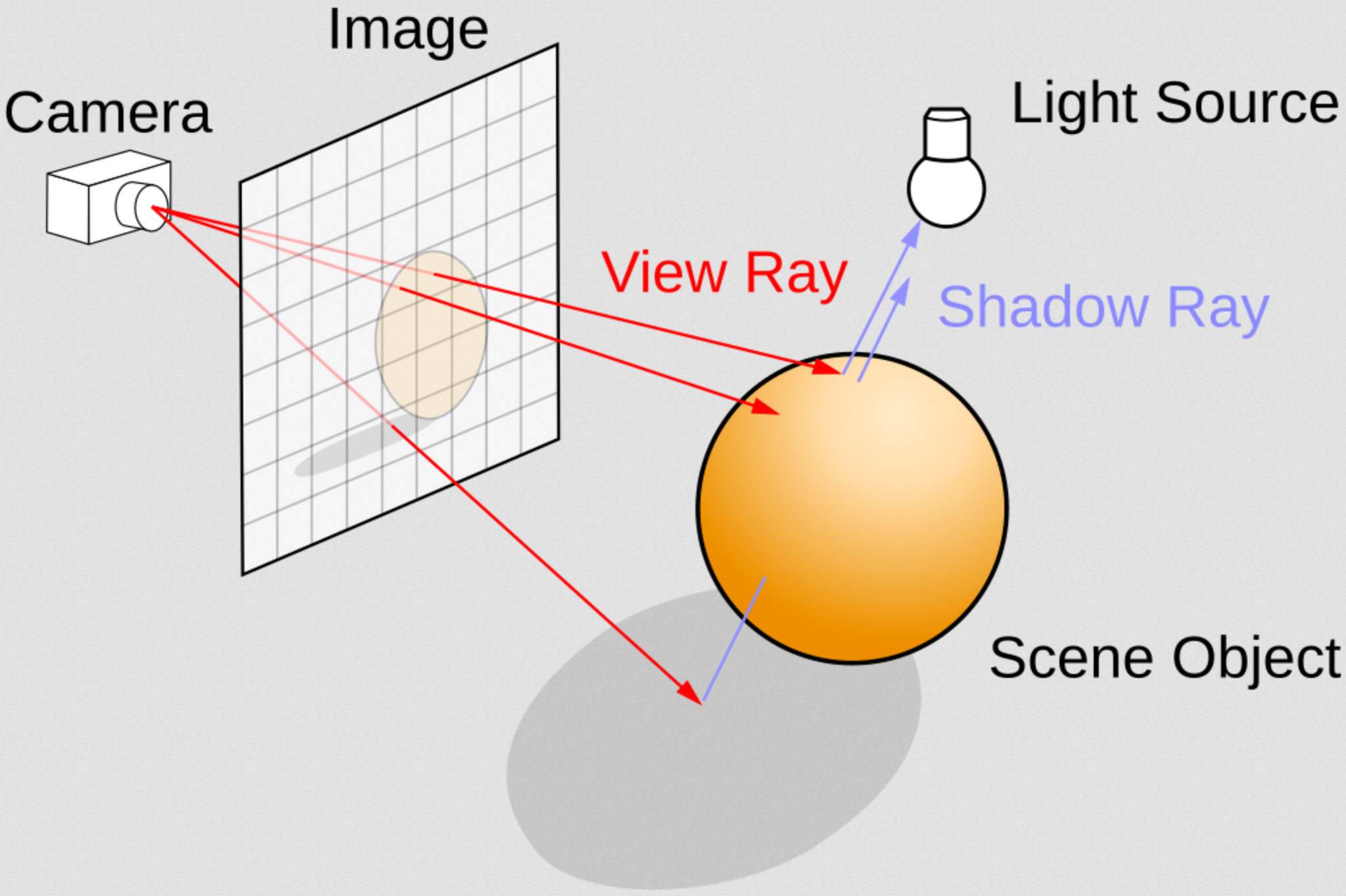
If realism is the main objective, the biggest alternative is Ray Tracing, or similar methods like Path Tracing. In these techniques, the light rays are simulated realistically, focusing not on speed but on accuracy. These techniques have been commonplace in non-real-time applications like movie production for decades, in parallel to rasterization, as even on limited hardware the results display an ability to reconstruct realistic lighting effects and shadows is astounding. By directly emulating the natural behavior of light rays, using not 3D projections but intersection functions on more mathematically defined 3D scenery, the resulting images automatically include effects such as indirect lighting, reflections and diffraction, hard and soft shadows and more. But, as mentioned, this technique is incredibly slow. Even with optimizations and intelligent use, real time rendering is considered an open problem, unless you leverage hardware acceleration, like the recent Nvidia RTX series.

There are a bunch more techniques for rendering beyond these two, but the one that got me interested (and I found in some YouTube tutorials for a couple of years ago) is Ray Marching. In Ray Marching, the rays do not directly emulate light rays and do not use intersection functions to calculate collisions with the environment. Instead, a Signed Distance Function (SDF) is used to estimate the minimum distance for the ray to advance, iteratively. The SDF encodes information about the scene’s geometry by allowing us to calculate the minimum safe distance for a ray to advance, in any direction, before they might collide with any geometry. Similar to using an echo to perceive how far objects around you are.

Rays, usually one per pixel, start from the camera, similar to ray tracing. But instead of directly computing collisions and reflecting rays, these move in steps. At each step, they compute the SDF at their current location and advance the resulting amount. Collisions are hard to detect as rays move iteratively, so a threshold is defined to identify when a ray is “close enough”. The resulting method is faster than Ray Marching, although not as fast or efficient as Rasterization, and requires a unique encoding for the world geometry, as meshes are not directly usable in these solutions. One special advantage of Ray Marching is how its space can be bent and deformed to create unique environments and spaces.
The SDF can be enhanced in multiple ways, encoding new and unique effects that are complex to render in traditional graphics, such as soft geometry mixing, ambient occlusion, fractal geometries and more.
If you want to learn more in detail about Ray Marching, both the theory behind it and how create unique effects, these are some great resources:
- Inigo Quiles’ Blog, the absolute master of Ray Marching
- kishimisu’s ‘An introduction to Raymarching’
- The Art Of Code’s ‘Ray Marching for Dummies!’
- Painting with Math: A Gentle Study of Raymarching
- Raymarching workshop
If you’re curious what I made, keep reading.
The past
This is another old project of mine. The first version dates back to around 2022, always in LOVR, but the code was pretty ugly. I later decided to revisit the idea and reorganized everything, while trying to better understand the topic.
Patching the code into compatibility with the newer versions was not as bad as I feared, mostly involving finding how various variables and commands got renamed. Then some cleanup of comments and variable names. Why do graphics programmers seem to like using single letter names so much? A bad habit shared by mathematicians.
The code is constructed as a shader, the Vertex stage does very little, focusing only on producing the required pos and dir vectors. These tell the rays where to start and where to go, and are linked with the user’s movement in VR.
As you can intuit from the comments, this was given me by the main developer a long time ago, and I don’t quite understand how it works. It also relies on having a certain number of objects be drawn by the shader, or it does not work.
//precision highp float;
out vec3 pos;
out vec3 dir;
vec4 lovrmain() {
  // Extract some form of X and Y coordinate for each pixel
  // Why `VertexIndex` ??
  float x = -1 + float((VertexIndex & 1) << 2);
  float y = -1 + float((VertexIndex & 2) << 1);
  // Normalie from [-1, 1] to [0, 1] and store in UV vector
  UV = vec2(x, y) * .5 + .5;
  // Take that back and use them for the Ray, now a (x, y, -1, 1)
  vec4 ray = vec4(UV * 2. - 1., -1., 1.);
  // Get the camera positon as a vec3 by taking the negative of the translation component and transforming it using the rotation component
  pos = -View[3].xyz * mat3(View);
  // combine the rotation component of the projection matrix and of the view and the ray to get the out direction
  // How?
  dir = transpose(mat3(View)) * (inverse(Projection) * ray).xyz;

  // why?
  return vec4(x, y, 1., 1.);
}
The mysteries clear up a little with the Fragment shader. This is where the actual Ray Marching happens. The positions produced by the vertex stage are iterated over, applying the relevant affects and rendered into colors. A general skeleton of the code might be:
float GetDist(vec3 p) {
    //secret sauce
}


// Main RayMarch loop
vec2 RayMarch(vec3 origin, vec3 direction) {
    float distance=0.; // total distance
    int i=0; //iternations
    // over GetDist function until
    for(i=0; i<MAX_STEPS; i++) {
        vec3 position = origin + direction * distance;    //get new DE center
        float displacement = GetDist(position);
        distance += displacement; // update distance

        // stop at max distance or if near enough other entity
        if(distance > MAX_DIST || abs(displacement) < SURF_DIST) break;
    }
    // Return number of steps and distance travelled as a pair of loats
    return vec2(float(i), distance);
}

vec4 lovrmain() {
    vec3 position = pos;
    vec3 direction = normalize(dir);

    vec2 raymarch_result = RayMarch(position, direction);
    float steps = raymarch_result.x;
    float dist = abs(length(raymarch_result.y));
    vec3 p = position + direction * dist;

    //vec3 col = vec3(dif);
    float col = 1.0;
    col -= (float(steps)/float(MAX_STEPS));
    col -= float(dist)/float(MAX_DIST);


    return vec4(vec3(col), 1.0);
}
The lovrmain handles normalizing values and creating the output colors, while the RayMarch function manages the iteration loop.
The real magic happens inside GetDist. Here the ray’s next step is calculated, so whatever is here defines the behavior of the scene.
If we use, for example, a sphere and a box, and we intersect them we can get:
// return distance from a box at positon pBox, of size sizeBox from position p. No rotation
float DEBox( vec3 p, vec3 pBox, vec3 sizeBox ){
  return length(max(abs(p - pBox) - sizeBox, 0.));
}

//return distacnce from a sphere at pSphere, radius rSphere, position p
float DESphere(vec3 p, vec3 pSphere, float rSphere){
    return length(p - pSphere.xyz) - rSphere;
}

float GetDist(vec3 p) {
    vec3 zero_pos = vec3(0., 0., 0.);
    vec3 sizeBox = vec3(.5);
    float box = DEBox(p, zero_pos, sizeBox);
    zero_pos.x += .5 * sin(0.5*time);
    zero_pos.y -= .6 * sin(0.4*time);
    float sphere = DESphere(p, zero_pos , .65);
    return max(box, -sphere);
}

vec4 lovrmain() {
...
    vec2 col = vec2(1.0);
    col.r -= float(dist)/float(MAX_DIST)+(float(steps)/float(MAX_STEPS));
    col.g -= float(dist)/float(MAX_DIST);
    return vec4(col, col.g, 1.0);
}

The scene depicts an oscillating being subtracted from a cube. No need to create new meshes, procedurally or anything. The rays calculate the combination of the geometries and render the accurate result directly. Obviously any physics requires either a novel approach, an underlying mesh model or something else, but we’re here for the looks.
The additions in lovrmain are to render more interesting colors.
The variable dist is the total distance walked by the ray, while steps is the number of iterations.
This allows us to shade distant areas darker, and add a slight blue glow near the surface, as rays passing ear a surface will have a higher number of steps.
This approach can be used for multiple effects such as glow or ambient occlusion, by leveraging information about the ray’s path in the scene.
We can also compute a surface normal and use that to calculate a light, if desired:
// compute normal based on partial derivatives of the distance function
vec3 GetNormal(vec3 p) {
    // get distance at the point p
	float d = GetDist(p);
    // offset used to extract a simple partial derivative
    vec2 e = vec2(.001, 0);

    // compyte distances in positions very nearby p, subtract them from the orignal distacne
    vec3 n = d - vec3(
    GetDist(p-e.xyy),
    GetDist(p-e.yxy),
    GetDist(p-e.yyx));
    // the results is an approximation of the normal of the surface that was closest.
    // normalize the result and return
    return normalize(n);
}

// used to compute lighting effects
float GetLight(vec3 p) {
    vec3 lightPos = vec3(0, 0, 0);
    // rotate light
    lightPos.xz += vec2(sin(time), cos(time))*2.;
    // get positions of light and surface normal
    vec3 light_vector = normalize(lightPos-p);
    vec3 surface_normal = GetNormal(p);

    // Basic phong model
    float dif = clamp(dot(surface_normal, light_vector), 0., 1.);
    return dif;
}

vec4 lovrmain() {
...
    // Get light iontensity at final position p
    float dif = GetLight(p);
    // Combine directional light and diffuse light into a final color
    vec3 diffuse_light = vec3(0.09, 0.06, 0.15);
    vec3 direct_light_color = vec3(0.8, 0.95, 0.98);
    vec3 col = dif * direct_light_color + diffuse_light;
    // Add effects reflecting distance and surfaces
    col -= 0.85*float(dist)/float(MAX_DIST) + 0.06*(float(steps)/float(MAX_STEPS));
    // Color the pixel
    return vec4(col, 1.0);
}
We can avoid tinkering with the Ray March loop here and instead focus only on the final ray position. A normal is obtained with a simple linear approximation, not very efficient but very flexible. Then we use a simple Phong model of the light to compute the direct light. This is combined with a color and a diffuse term to render a decent looking scene.

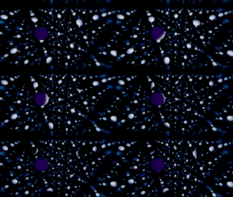
Here we also added a spatial repetition to the spheres, but not the light source, as it only applies to the inner marching loop. Thus, we have a single light, and each sphere is illuminated individually. Notice the absence of indirect shadows, as the Phong model does not include them. We can see brighter areas in the direction of the light, but the spheres do not block the light and will not cast a shadow. Implementing these require much more work, either in logic on computing.
Personal
This first one is very similar to the Phong example from before, using a moving light in repeating spheres.

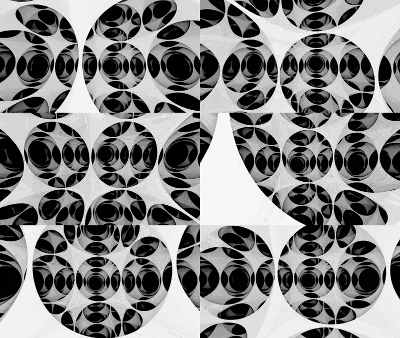
Here the infinite grid is made of cubes with subtracted spheres.
Looks cool and was one of my first decent environments.

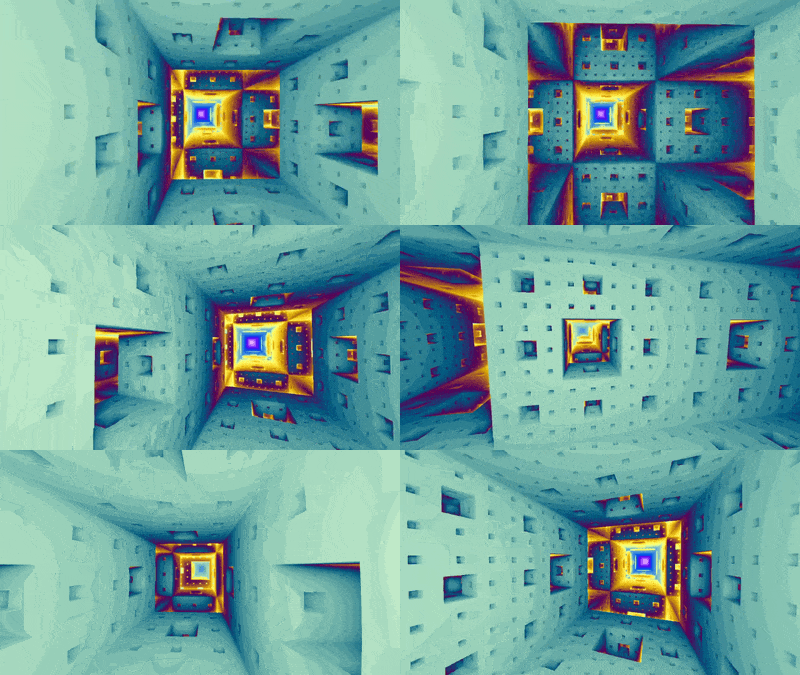
This is a Menger Sponge, a 3D fractal.
I got the idea after reading both Quilez’s blog and Code Parade’s videos about ray marching and fractals.

Bad News
While this is great and cool and has tons of potential, I’m faced with an issue: performance.
Simply put, I can’t get even a simple scene to Ray March at full speed in headset. Sadly, high resolution, high frame rate and limited power are likely a deadly combination for a technique where each pixel is an independent ray moving in space. While there are a lot of techniques around optimizing complex scenes, I can’t find much to try and optimize Ray Marching at its fundamental level, likely due to its simplicity. How much can you really optimize a single loop?
It’s also quite challenging to actually study the exact performance issues and hurdles of the method, considering I work on Linux and Oculus does not agree on the topic. Their tooling is all Windows exclusive and not very detailed in documentation, in my experience. I also generally lack the knowledge to effectively track down potential issues, beyond the algorithm’s logic, even using desktop software like RenderDoc. I do have a couple ideas, but those are for a future version, maybe.
As always all the code is available on GitHub.